Disclaimers: I am not a health care professional. Nothing in this article is medical advice. The links contained in this article to products on Amazon are affiliate links. Purchase of products via these links will produce a commission for me, and I thank you for your support.
What is this project?
Short story: The project is a WiFi connected pulse oximeter that enables us to remotely monitor and record the statistics from the oximeter.
An oximeter is a sensor that (supposedly) measures the oxygen saturation of the blood from the observed subject. There are tons of articles on how this sensor works with Arduino. That is great if you want to make a miniature hobbyist pulse oximeter, but I wanted more functionality than that. This project includes the following features:
- Reads Oxygen Saturation and Heartrate
- Connects to a WiFi network
- Reports O2 Saturation and Heart rate over MQTT
The final piece of this project is the use of an IoT management platform to monitor and record the statistics from the device. This is what the MQTT protocol is reporting to. In our case we’re using OpenHab which is very quick and easy to deploy with the Openhabian distribution, but I assume you could use other systems such as Home Assistant to do something quite similar.
I want to stress that, like a lot of my projects, this is a hacky prototype that I developed rapidly. There’s plenty of room for improvement.
Why this project?
This project came to mind for me when medical professionals were commenting on the symptoms and impacts of the COVID-19 virus. One of the repeated concerns from health care professionals early on was the deterioration of oxygen saturation leading to a rapid “silent hypoxia” also referred to colloquially as “walking pneumonia.” The drop in oxygen saturation with COVID-19 patients is a main cause of ICU treatment and need for ventilator assistance. Health care professionals have repeatedly stated that monitoring oxygen saturation (O2 Sat) has been a key in early treatment before the patient’s condition deteriorates. I’m not going to bother linking articles discussing this because they’ve been so prevalent that I feel everyone should already be aware of this information. If not, I encourage the reader to do some web searches for this subject and independently verify.
I’ve read several articles in which doctors suggest individuals obtain for themselves a pulse oximeter as a diagnostic tool for home care, similar to how we all have home medical thermometers. These devices are usually pretty cheap and you can find them on Amazon. I purchased one of these units, myself. However, this device didn’t allow me to track values over time, and only displayed the data in real time on the device OLED. I wanted a device that was intended for supporting observation of an isolated individual that could track historical data.
I really seriously need to stress that this project is not a device intended to diagnose, treat, or cure any illness or ailment. This is a project using electronics hobbyist hardware. It is not a medical grade device. It’s likely to be inaccurate and inconsistent. I can’t take any responsibility for the use or misuse of this information. All that aside, I’ve found the project informative and I’m glad I have it in my toolkit.
This project enables a person to view and record the heart rate and Oxygen saturation of an individual who may be isolated without the need for contact.
Parts:
The full project for this device requires the following hardware:
- Wemos D1 mini – this is our main device
- GY-30100 – this is our pulse oximeter
- Jumper wires– (in my case male to female)
- Soldering tools including an iron, solder, and cleanup supplies.
- A battery or power source for the D1 mini, typically connected via a usb micro cable.
- A WiFi network to connect the device to
- An OpenHab system which may require a computer or Raspberry Pi
In order to make this practical to wear you need some sort of housing around the sensor to affix to a finger. I created a rough case design out of primitives that can be printed with a 3D printer. You can find that project on Thingiverse here. There are other designs for other sensors, and many that are better than the rough design I created, but this one is the one that I cranked out to fit this project and it prints pretty fast. The version I published to Thingiverse includes two holes for machine screws to affix the O2 sensor in place, but I didn’t have any machine screws that size on hand (“Doh!”), so I printed a filled in case and ran screws through it. Like I said, quick and dirty. It’s not going to win any prizes for aesthetic. The case is held on the finger with a simple rubber band or hair tie elastic. The bottom line is that you get the idea.
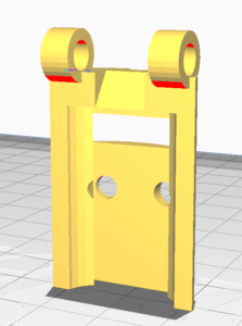
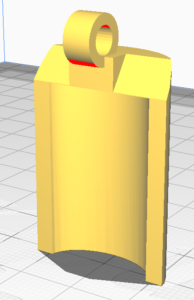

(Images: 3d Printed case design bottom, without sensor, view top. with sensor, view bottom, with sensor, view top)
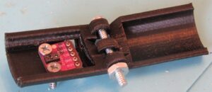
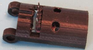
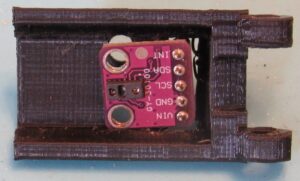
(Image: 3d Printed case design, assembled with sensor)
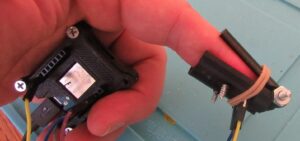
(Image: 3d Printed case with elastic on finger with Wemos D1 Mini Connected. Operational.)
If you don’t have a 3d printer, I’d simply say “get imaginative.” You can do it.
You may also want to create a case for your Wemos D1 Mini.
Let’s get started:
Start by addressing the hardware issues first. Solder your pinouts on your Wemos D1 Mini and your GY-30100. I used female connections on the Wemos D1 Mini pointing UP, that is on the side of the wifi chip, and on the Oximeter I used male pins pointing DOWN, that is on the opposite side of the LED and IR sensors on the oximeter chip. This configuration lets me use the 3D printed cases I’ve chosen.
Print 3D parts and assemble. You can work on the initial programming of the Wemos D1 while you wait for the print. I recommend printing the oximeter housing in opaque black since light appears to have an impact on the sensor.
The Wemos D1 Mini:
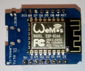
(Image: Wemos D1 Mini)
Arduino IDE doesn’t support the ESP8266 outright. You’ll need to prepare you
r environment for working with the hardware. There’s a great Instructable here that will help with this.
(Image: Wemos D1 Mini)
I was originally introduced to this little device through HackerBoxes and I love this thing for homebrew IoT projects. It’s an Arduino capable board with wifi built in and it’s capable of being flashed with Tasmota firmware to make a lot of projects really easy, really fast. In this project however, we’re using straight Arduino sketch code, so nothing too fancy. You’ll need the Arduino IDE and a bit of proficiency with the IDE.
With any Arduino project, it’s a good idea to connect the device and run a simple “Blink” sketch to the device to verify your connection, device, and programmer are working properly before continuing. This lets you troubleshoot the basic things before moving on to the more complicated issues.
After you’ve verified that you have no issues interfacing with your Wemos D1 mini, You are going to need additional libraries for this project:
WiFi
mqtt
Wire the Wemos D1 Mini and the Oximeter sensor.
Pinouts:
| Wemos | GY-30100 |
| 3.3v | VIN |
| G | GND |
| D1 | SCL |
| D2 | SDA |
And now for the dirty meat of this project, the code:
I can’t take credit for this code. I found several examples of each of these functions through multiple searches and stitched them together to make this code functional, but it’s not original. You’ll obviously need the prerequisite libraries such as the MAX30100_PulseOximeter. Review the includes and obtain the necessary libraries.
______________________________
#include <Wire.h>
#include <ESP8266WiFi.h>
#include <PubSubClient.h>

#include "MAX30100_PulseOximeter.h"
#define REPORTING_PERIOD_MS 5000
PulseOximeter pox;
uint32_t tsLastReport = 0;
// Network SSID
const char* ssid = "YOURWIFINETWORKNAME";
const char* password = "YOURNETWORKPASSWORD";
// MQTT
const char* mqttServer = "OPENHABIPADDRESS";
const char* mqttUsername = "OPENHABMQTTUSERNAME";
const char* mqttPassword = "OPENHABMQTTPASSWORD";
char pubTopic[] = "MQTTTHINGTOPUBLISHAS";
float bpm;
int os;

WiFiClient espClient;
PubSubClient mqttClient(espClient);

long lastMsg = 0;
char msg[50];
int value = 0;

void onBeatDetected()

pox.setOnBeatDetectedCallback(onBeatDetected);
}

void loop()
{
// Make sure to call update as fast as possible
pox.update();

pox.setOnBeatDetectedCallback(onBeatDetected);
}

void loop()
{
// Make sure to call update as fast as possible
pox.update();
if (millis() - tsLastReport > REPORTING_PERIOD_MS) {
Serial.print("Heart rate:");
Serial.print(pox.getHeartRate());
Serial.print("bpm / SpO2:");
Serial.print(pox.getSpO2());
bpm = (pox.getHeartRate());
os = (pox.getSpO2());
Serial.println("%");
Serial.println(bpm);
Serial.println(os);
//here you need to specify your items to publish to. Replace PUBTOPICNAME with your destination device.
mqttClient.publish("PUBTOPICNAME/os", String(os).c_str());
delay(100);
mqttClient.publish("PUBTOPICNAME/bpm",String(bpm).c_str());
tsLastReport = millis();
// mqttClient.publish()
}
}

if (millis() - tsLastReport > REPORTING_PERIOD_MS) {
Serial.print("Heart rate:");
Serial.print(pox.getHeartRate());
Serial.print("bpm / SpO2:");
Serial.print(pox.getSpO2());
bpm = (pox.getHeartRate());
os = (pox.getSpO2());
Serial.println("%");
Serial.println(bpm);
Serial.println(os);
//here you need to specify yo

pox.setOnBeatDetectedCallback(onBeatDetected);
}

void loop()
{
// Make sure to call update as fast as possible
pox.update();
if (millis() - tsLastReport > REPORTING_PERIOD_MS) {
Serial.print("Heart rate:");
Serial.print(pox.getHeartRate());
Serial.print("bpm / SpO2:");
Serial.print(pox.getSpO2());
bpm = (pox.getHeartRate());
os = (pox.getSpO2());
Serial.println("%");
Serial.println(bpm);
Serial.println(os);
//here you need to specify your items to publish to. Replace PUBTOPICNAME with your destination device.
mqttClient.publish("PUBTOPICNAME/os", String(os).c_str());
delay(100);
mqttClient.publish("PUBTOPICNAME/bpm",String(bpm).c_str());
tsLastReport = millis();
// mqttClient.publish()
}
}

//ur items to publish to. Replace PUBTOPICNAME with your destination device.
mqttClient.publish("PUBTOPICNAME/os", String(os).c_str());
delay(100);
mqttClient.publish("PUBTOPICNAME/bpm",String(bpm).c_str());
tsLastReport = millis();
// mqttClient.publish()
}
}

{
Serial.println("Beat!");
}

void setup()
{
Serial.begin(115200);

delay(6000);
Serial.println(espClient);
// Connect WiFi
WiFi.hostname(pubTopic);
WiFi.begin(ssid, password);
mqttClient.setServer(mqttServer, 1883);
if (mqttClient.connect(pubTopic, mqttUsername,mqttPassword)){
Serial.println("mqtt Connected");
}
else{
Serial.println("MQTT Connection failed ");
Serial.println(mqttClient.state());
}
Serial.print("Initializing pulse oximeter..");
// client.connect(clientId.c_str(), mqttUsername,mqttPassword)
// Initialize the PulseOximeter instance
// Failures are generally due to an improper I2C wiring, missing power supply
// or wrong target chip
if (!pox.begin()) {
Serial.println("FAILED");
for(;;);
} else {
Serial.println("SUCCESS");
}
pox.setIRLedCurrent(MAX30100_LED_CURR_7_6MA);

// Register a callback for the beat detection
pox.setOnBeatDetectedCallback(onBeatDetected);
}

void loop()
{
// Make sure to call update as fast as possible
pox.update();
if (millis() - tsLastReport > REPORTING_PERIOD_MS) {
Serial.print("Heart rate:");
Serial.print(pox.getHeartRate());
Serial.print("bpm / SpO2:");
Serial.print(pox.getSpO2());
bpm = (pox.getHeartRate());
os = (pox.getSpO2());
Serial.println("%");
Serial.println(bpm);
Serial.println(os);
//here you need to specify your items to publish to. Replace PUBTOPICNAME with your destination device.
mqttClient.publish("PUBTOPICNAME/os", String(os).c_str());
delay(100);
mqttClient.publish("PUBTOPICNAME/bpm",String(bpm).c_str());
tsLastReport = millis();
// mqttClient.publish()
}
}
________________________________
You’ll need to insert your variables in the proper locations.
Once you compile and upload the sketch to the target system, you’ll be able to connect via serial and verify that your oximeter is working.
On to making this project (more) functional:
OpenHab….
I’ve been working with OpenHab for several months now and I can comfortably say it has a steep learning curve. I can also comfortably say it is an incredibly powerful system that with the proper knowledge can control, automate, record, and notify as you would expect from an industrial control system. Succinctly, OpenHab is a Free, Open Source SmartHome automation platform. A system of this nature is quite revolutionary for home tasking and automation. Anybody working with tech on a regular basis can probably benefit greatly from such a system if properly implemented.
There are quite a few prerequisite setups necessary for this project to work. Rather than re-writing how-tos and documents, I’ll be linking to much of the initial information.
Configuring OpenHab for meaningful usage:
OpenHab has several bindings and features that will provide useful for us in this project.
We’re going to be using the NETWORK binding to verify that the device is online.
We’re going to be using the MQTT binding to receive the data from the device.
We’re going to be using the InfluxDB persistence to record the data from the device.
and finally..
We’re going to be using the Grafana add on to display the recorded data.
OpenHab: NETWORK
The network binding on OpenHab is a basic tool for determining networked devices statuses. The binding can display online status via ping check, last seen time, and latency. The most relevant for us is online status since this is an IoT type device on WiFi. We want to ensure that it’s plugged in and network is working. In order for this to be useful, you’ll need to set a reservation for the device’s IP address in your router. This is specific to your hardware. Once you’ve established a set IP address for your wifi oximeter device you can set the NETWORK binding.
We could develop rules for alerting, notifications, recording conditions and so on, but for this project, just being able to display if the device is on Network is acceptable.
Read More about the OpenHab Network Binding
OpenHab: MQTT
MQTT is a lightweight protocol for communicating between IoT devices. It can be used to send and receive data, so you can use it to report data as well as send commands. In this case, we are simply reporting data from the IoT device to the OpenHab MQTT broker.
You can learn more about MQTT protocol here
You can learn how to set up your MQTT broker in OpenHab here and here.
The code example requires you to set the IP address of your OpenHab instance where your broker is running and the credentials you will need to communicate with the broker.
This is one of the primary functions with this project. With it, the oximter values reported over serial will also be sent to our MQTT broker.
You will need to create a THING and an ITEM binding in OpenHab to hold and display the values received in OpenHab.
It’s important that you understand how THING and ITEM creation works in OpenHab to setup the locations for receiving the data in OpenHab.
The documentation for that can be found here:
Things Concepts and Configuration:
https://www.openhab.org/docs/concepts/things.html
https://www.openhab.org/docs/configuration/things.html
Items Concepts and Configuration:
https://www.openhab.org/docs/concepts/items.html
https://www.openhab.org/docs/configuration/items.html
Note that you’ll have to use a text based files on the OpenHab system in order to make this fully functional. This means remote access via SSH if your OpenHab system is headless. You can not do everything mentioned here with the stand alone PaperUI.
In my example named my Oximeter thing ‘regophim’ and the items holding values ‘os’ for oxygen saturation and ‘bpm’ for beats per minute. The end result for my mqttpublish locations becomes regophim/os and regophim/bpm in this example.
Once we have an MQTT binding and THINGS and ITEMS for the Wemos to report to we should be able to see the device values published in the Control Section under the THING in the OpenHab PaperUI.
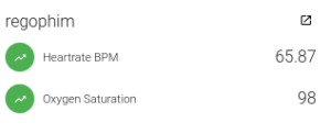
(Image: PaperUI output example from our device)
OpenHab: INFLUXDB
The THING and ITEM information display for OpenHab will display the real time or last read values of the MQTT reported value, but this doesn’t allow us to see anything beyond that value. For that we need to record those values. OpenHab handles such activity with the “Persistence Binding.” This is essentially storing data points in a chosen database format.
OpenHab has several options for persistence, but OpenHab handles some options better than others. I chose to use InfluxDB as my default option and I find that works very well for virtually everything that I record for historical and graph representation.
You will need to create a PERSISTENCE value for tracking the data.
MORE ON PERSISTENCE IN OPENHAB
OpenHab: GRAFANA
While OpenHab’s HabPanel has the ability to graph a single data point in a simple widget called “chart” it pales in comparison to the presentation abilities presented by Grafana. If you are in tech you are probably a bit of a data geek. If well presented data is uncharacteristically satisfying to you, you are going to enjoy Grafana. I can only describe the myriad of possibilities of data tracked by OpenHab and Grafana’s presentation as “sexy.” This project barely touches the capabilities of this, so I really hope that if you set up an OpenHab system that you leverage this powerful presentation mechanism more than I’ve done here.
Setting up graphs for this project once the InfluxDB data points have been populated is very simple.
An OpenHab Community article on Grafana and InfluxDB in OpenHab
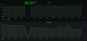
Once we’ve setup InfluxDB, persestance, and Grafana, we get graphical representation of historical data.
In this sample, I’m powering the Wemos with a 5v/2.4A 15kmAh phone recharging battery pack powered off microUSB. I go from sitting, to walking around the house to close some windows, back to sitting back down. You can see the activity reflected in heartrate over time.
The end result…..
The end result of this project is an inexpensive Wifi connected device that measures O2 Saturation and Heart rate of the subject without the need for a person to be in the same room with them.
I don’t have a medical grade device to compare the functionality of this device to, but I do have a consumer grade device that I mentioned earlier. This allow me to compare my home-brewed hardware to a supposedly “known good” device. The results were fairly consistent when situations were comparable.
Depending on where the sensor is and how it is situated, readings may be more or less accurate. I tested embedding this in a pair of gloves at the base of a finger and got wildly inaccurate readings at times and spot on readings at others. Understanding how the sensors in the project work will also be beneficial to ensuring the best possible reads. Outside light, including IR light, will have an adverse impact on the accuracy of the sensor.